This is Chapter XVIII from the 1917 edition of Naval Ordnance, a text book for officers of the United States Navy. You may view the several plates separately:
Published by the United States Naval Institute
Ammunition-rooms, magazines.
With the exception of the detonators and dry gun-cotton primers for torpedoes, all ammunition, of whatever character, is stowed in specially constructed rooms set apart for that purpose alone; a few projectiles are often stowed in racks around the gun-emplacements or below decks, where they can be expeditiously supplied to all guns in emergencies; and in turrets and below the turret floors.
The ammunition-rooms are commonly distinguished in name by the kind of ammunition they contain, as well as by their regular numbers; for example, compartment A-37-M is one of the forward 12-inch magazines; compartment D-33-M is the small-arm magazine.
Flooding and draining.
All ammunition-rooms are watertight compartments. Arrangements are made for admitting seawater to each room. Those situated above the water-line have pipes leading from the fire-main; those situated below the water-line have pipes leading from a sea-valve. The flood-pipe in shell-rooms is a simple pipe with one opening. The pipe in powder-magazines has many small holes on the underneath side, and is called a sprinkler. Sprinklers are also fitted over gun-loading positions in turrets, and over powder-loading positions in handling-rooms. In every case the pipe, both flood-pipe and sprinkler, must be of sufficient size to fill the magazine in 20 minutes. This requirement necessarily varies the number of holes in the sprinkler pipes, depending upon the size of the magazines.
On the pre-dreadnought types of ships the flood-pipe leads from the outer skin of the ship (sea-valve), below the water-line, directly to a flood-valve which is worked either in the magazine itself or from the berth-deck. A spindle leads from the pipe to a plate on the berth-deck, and ends in a square section on which is shipped a large key turning the valve. This key or wrench is kept near at hand in a locked rack, the key of which is kept with the magazine keys. In some cases the socket in the deck, in which is the head of the spindle, is locked by a padlock, the key of which is kept with the magazine keys. Magazine keys are kept in the captain's cabin.
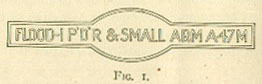
The deck-plate is stamped with the name and the compartment number of the room it floods, and an arrow-head indicates the direction in which the valve opens. In addition, a specially shaped plate, with a red ground, secured to the beam above, gives the same information. For example, see Fig 1.
The air escapes from the magazine through the exhaust ventilating-duct; if none is fitted, a special escape-pipe is provided to allow the room to fill. Those compartments flooded from the fire-main have relief-valves to prevent the accumulation of a pressure that would make the bulkheads collapse.
Ammunition-rooms in the hold drain into bilge-wells, from which suction-pipes lead to drain-manifolds. Upper compartments sometimes have individual drain-pipes to drain wells or lower compartments. In most cases they can be freed of water, that happens to find its way into them, only by portable pumps. No recent ships have any means of draining magazines and shell-rooms other than portable pumps.
Later Ships.- In the later ships, instead of each magazine and shell-room being flooded separately, they are divided into groups, and flooded by groups, by turning one valve. Each compartment is fitted with a cut-out valve, so that the whole group or any certain compartments in a group may be flooded. The cut-out valves can be operated only from the magazines.
Method of testing.- It is only necessary for testing-purposes to determine if, when the valve is opened, water will enter the pipe in the magazine. Therefore these pipes are fitted with a cap which is secured to the end of the pipe when testing. The valve is then opened, either from the berth-deck or from the magazine, and ad magazine bucket is held under the drain-cock fitted on the pipe near the cap. The drain-cock is then opened, and if water comes out through the cock the flooding system is in good order.
Testing sprinklers.- There is no way by which the sprinkler can be tested without letting the water into the magazines. The valve on the sprinkler pipes which controls the water can however be tested.
Ventilation.- The adoption of a smokeless powder which, in the process of manufacture, is colloided with a very volatile liquid, makes the subject of ventilation a very important one; the ether fumes are inflammable and must be carried off and, in addition, the powder must be kept cool. To this end, every ammunition-room is fitted to receive, directly from the ship's artificial ventilating system, a supply sufficient to renew the air once in about eight minutes. A natural exhaust-pipe of greater area than the supply-duct is placed in each room as far away from the supply as possible; the upper end is carried up at least above the berth-deck and terminates in a goose-neck covered with wire mesh. When ammunition-hoists open directly into the magazine, the trunk of the hoist itself is used for natural exhaust ventilation; a goose-neck outlet, covered with wire mesh, is fitted at a height above the berth-deck. Piping in ammunition-rooms is generally of brass.
The question of ventilation is not fully settled at this time. In ships that are not fitted with magazine refrigeration-plants the ventilation system is as outlined above. Where refrigeration has been installed, however, various arrangements have been made, from no ventilation at all (as in the case of those ships using ethyl-chloride refrigerating-machines) to the ordinary amount of ventilation provided by a blower operated on either the closed or the open system - that is, the blowers drawing the supply of air either from the magazine or from the open air.
Refrigeration.- The question of magazine-refrigeration first occupied attention about 1899, on the advent of smokeless powder. At this time an experimental system was installed in the Illinois. This consisted of dense-air machines having brine-pipes in the magazines. The magazines were not insulated, and the installation was not a success. From 1899 to 1908 the question was not actively considered, but in 1908 a magazine-refrigeration system similar to that being installed in British ships was experimented with in the Iowa. This consisted in installing a cooling-box outside the magazine, with the cold air to the magazine-room on a closed circuit. This was considered generally satisfactory, and was followed in 1909 by a similar installation on the Ohio. The ice-machine was an electrically driven CO2 machine. Both in the Iowa and in the Ohio the magazines were insulated.
The North Dakota and Delaware were the next ships to have magazine-refrigeration. On these ships dense-air steam-driven machines were installed. The dense air circulated through cooling-boxes located outside the magazines, and the air to the magazines was circulated over the coils in the cooling-boxes. The ventilation-blower could draw the supply either from the magazines or from the open air. This installation was not entirely satisfactory, and an entirely new system was experimented with on the midship magazines of these vessels.
This new system consists of an ethyl-chloride ice-machine in which the cold brine is circulated directly to the magazines, no ventilation being provided. The magazines are fitted with coils, drip-pans, etc, and the system has proved satisfactory.
The following table shows the types of installations that have been made:
| Machine | Motive Power | Cooling box | Brine in Magazine |
| CO2 | Electric | Yes | No |
| CO2 | Electric | No | Yes |
| C2H2O | Electric | No | Yes |
| Air | Steam | Yes | No |
The air-machines have not been satisfactory except where thick insulation has been used.
The original requirements as regards temperature were that the magazines should be kept not above 70º F., and as near 70º F. as possible. Experience has proved that a temperature of 80º F. is satisfactory, and all present installations are based on this temperature.
In the installation of magazine refrigeration-plants the following requirements when well met add to the efficiency of the plant:
(1) Decks and bulkheads to be well insulated by cork.
(2) Beams and stiffeners to be insulated by cork.
(3) All piping to be efficiently lagged.
(4) Number of supply-ducts to be left at a minimum, and with outlets 3 feet from the deck.
(5) Exhaust-ducts also to be left at a minimum, and to take from upper part of magazine.
(6) No cold-air piping must pass through heated compartments, such as machine-shop, evaporator-room, etc.
Lighting.- Each magazine and shell-room is lighted by one or more light-boxes, of standard navy pattern, which throw light in three directions through round ports covered with double glass plates. The boxes are water-tight, and are separate compartments opening only from the deck above or from some passage or compartment outside the magazine. The light-boxes each contain incandescent lamps and are arranged to burn candles if the maps fail; in the latter case, enough water to cover the bottom should be poured into the light-box.
The above holds for ships of the pre-dreadnought type. In all ships built since the South Carolina and Michigan the magazines and shell-rooms are lighted by bunker lights, either set into the bulkhead in a recess or attached to the bulkhead on the magazine side. They contain the incandescent lamp, and have no facilities for using a candle.
All magazines and shell-rooms are lighted from the magazine lighting-circuit.
The wing-passages or ammunition-passages in these ships are also very useful in transporting ammunition from one 12-inch handling-room to the other, in case of emergency - such as when one turret is disabled, while the other turret is running out of ammunition.
Recent designs.- In the recent designs of all big-gun ships, the location of ammunition-rooms is more complicated. Plate I shows the arrangement of magazines and shell-rooms, and ammunition passages, on the upper and lower platform decks of a dreadnought.
Taking the Delaware for example, all the turret handling-rooms are on the upper platform deck, with magazines and shell-rooms adjacent, and with ammunition-passages to adjacent turrets. On this deck the handling-rooms for the No. 1 and No. 2 turrets, and also for No. 4 and No. 5 are communicating. Magazine-rooms are also below the handling-rooms, on the lower platform deck, except for the No. 3 turret.
On the lower platform deck, an ammunition-passage runs from the magazine under the forward turret on both sides, to the 5-inch magazines and shell-rooms under the No. 3. turret. These ammunition-passages connect both forward and aft by athwartship passageways. At the ends of these ammunition-passages are situated the 5-inch magazines and shell-rooms.
The ammunition for the 5-inch guns is passed from the ammunition-rooms to conveyors in the ammunition-passages, which take it to the proper chain-hoist. These hoists are scattered along the length of the ammunition-passages, inboard, and supply the broadside guns.
The 5-inch magazines and shell-rooms for the forward and after guns are also situated on the lower platform deck forward and aft of the ends of the ammunition-passages, and the chain-hoists for the ammunition are situated in a small space outside the ammunition-rooms called the 5-inch handling room.
Rooms for naval defence mines, saluting powder, and small-arm ammunition are situated on the lower platform deck. The torpedo war-head room is in the hold.
The present practice in the new 14-inch gun ships is to do away with turret handling-rooms proper. All shells for the turret-guns are stowed (base up) in the turret and barbette. There is a powder handling-room adjacent to the powder passing-platforms. The magazine opened into the powder handling-rooms.
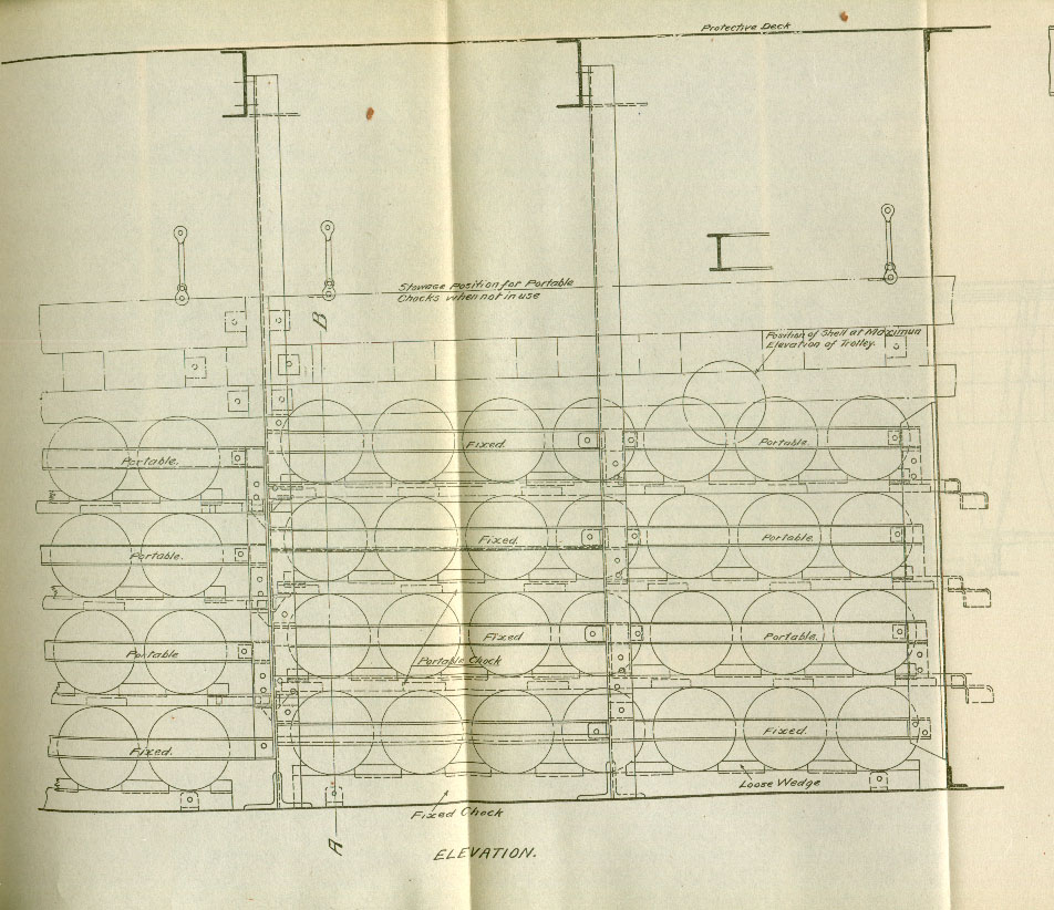
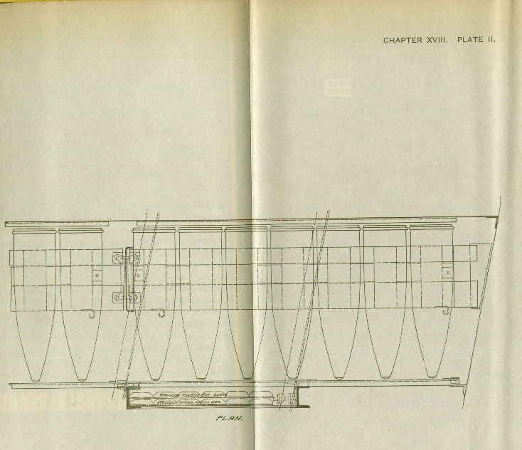
Plate II [Part 'A', Part 'B', Part 'C'] shows the method of stowing 12-inch and 14-inch shells. Note the magazine insulation.
Powder-tank stowage.- Powder-tanks are stowed in bins, usually on their sides. They should be stowed so that their contents can be removed without disturbing them. It is usual to arrange them, particularly those for the turret-guns, with their heads to the passage. The bins are built up from stationary vertical channels and rolling-boards, which are removed to get at the tanks. Bins are arranged in the different magazines with a view to accessibility in supplying powder to the hoist, and, where necessary, alleys are run between them. While the ship is rolling, projectiles, powder-tanks, and charges are more secure if stowed parallel with the keel, but the tanks and charges should be perpendicular to the passages. It has been found that when the tanks are stowed on end, the powder settles and stretches its bags; this has been so troublesome that the charge could be gotten into the gun only with great difficulty.
The new interlocking powder-tanks will not only save room by allowing the tanks to be stowed closer together, but will also be more accessible and save some weight.
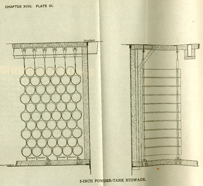
Plate III shows the latest method of stowing 5-inch powder-tanks. Note the magazine insulation.
The ammunition-rooms of small ships are simply arranged in two groups in the hold, forward and aft. The regular type of hoists are used to convey ammunition to the main battery, while whips are generally used to hoist the boxes of secondary-battery ammunition through the hatches.
For the efficient use of a ship's battery in action, the supply of ammunition is next in importance to the correct use of the guns. The excellence of the gun-pointers and crews will avail nothing unless they can receive the ammunition in exactly the proper way.
Save for a few projectiles, it is unsafe to stow any ammunition near the guns; in fact, it is imperative to stow it below the water-line in certain places, which may be a long distance from some of the guns. The problem, then, which varies in its intricacy in each class of ships, is to maintain a supply of ammunition to each gun - firing several rounds per minute - as fast as it is needed, without allowing it to accumulate on deck, as, for instance, which the gun to which a particular chain of supply is silenced. All practicable precautions against powder-explosions from the enemy's fire must be enforced.
Obviously, the simplest and surest solution of the problem is to install a magazine and shell-room directly beneath each gun, which hoists leading upward to it. This would involve placing a line of magazines along each side of the ship, extending the whole length of the machinery-spaces, which cannot be done, because many rooms would be too near sources of heat, and the space is not available. These restrictions, which complicate the problem on board ship, do not affect the question of gun-installation on shore, where space and weight are unlimited.
This ideal arrangement of individual magazines and hoists is, in general, attained only for turret-guns, which, as it happens, are mounted over spaces available for magazines; the tendency, however, is to provide a hoist for each main-battery gun and a sufficient number for the smaller pieces. The hosts cannot lead very obliquely, and in some cases ammunition must be transported by hand over considerable distances, both below and on the battery decks; however, it is the best that can be done, and the difficulty exists in all navies.
Ammunition stowage and supply is a problem to which the designer devotes much thought; but when he has exhausted his ingenuity in the finished ship, the question of efficient supply is only partially solved, because the more important part is concerned with the personnel rather than with matériel. It remains for the "powder-division" (which contains many good men, and many not suitable for work at the guns) to manipulate the machinery of supply to the best advantage. The best thought of the officers in direct command is needed at this point, and complete success will come only when all the details have been minutely and patiently worked out. Care in stationing every man according to his fitness will often give good results from a manifestly imperfect system.
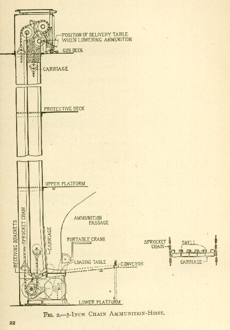
Ammunition-hoists for turret-guns were described in a previous chapter [not reproduced]. Fig 2. shows a 5-inch chain-hoist. The ammunition is brought from the magazines to the base of the hoist by an ammunition-conveyor. In some cases the chain-hoist is in the magazine.
Return to WWI The Maritime War
Return to WWI Archive main page.
![]()